Schematic 555 Timer Circuit Diagram / 555 Timer Tutorial The Monostable Multivibrator - Its name is derived from three 5k ohm resistors ,connected in series used in it.the timer ic can produce required waveform accurately.
Schematic 555 Timer Circuit Diagram / 555 Timer Tutorial The Monostable Multivibrator - Its name is derived from three 5k ohm resistors ,connected in series used in it.the timer ic can produce required waveform accurately.. Contact less car door left open reminder alarm. 555 datasheet 555 duty cycle 555 metronome 555 reset function 555 time delay relay inverted 555 timer pulse generator. The conventional 8 pin dip package is the most common, but a t metal can type is also available. The 555 timer is a simple integrated circuit that can be used to make many different electronic circuits. The 555 ic timer circuit above shows a very straightforward design where the ic 555 forms the central controlling part of the circuit.
In this category, we have handpicked some really useful 555 timer circuits which will be interesting to electronics engineering students and hobbyists alike. This circuit uses very basic components like 555 timer and 4017 counter. Although the schematic looks correct, this basic circuit may actually have a few negative aspects. 555 datasheet 555 duty cycle 555 metronome 555 reset function 555 time delay relay inverted 555 timer pulse generator. If a 10uf timing capacitor is used, calculate the value of the resistor required to produce a minimum output time delay of 500ms.
555 Timer Tutorial The Monostable Multivibrator from www.electronics-tutorials.ws 555 timers are very popular in electronics. The conventional 8 pin dip package is the most common, but a t metal can type is also available. The 555 timer ic is an integral part of electronics projects. The 555 is also very versatile, and can be used. 555 timer is an industrial standard ic existing from early days of ic. This enables the 555 to operate as a window detector. 555 timer, as the name specified, are the electronics circuits used for measuring time intervals.in this article, we will cover about 555 timers. This integrated circuit can be used in a variety of ways from which the basic one is to produce accurate and stable delays in electronic circuits.additionally, it is available in 8 pin dip and 14 pin dip.
This enables the 555 to operate as a window detector.
The 555 timer starts timing when switched on. The circuit will not repeat it's timing cycle if the push switch s1 will remain on or pressed, after a timing cycle is completed. In this pwm generater circuit, as we mentioned above we have used 555 timer ic for generating pwm signal. The block diagram of a 555 timer is shown in the above figure. In the place of the push switch s1 / trigger switch you can also connect the output of any project to trigger the timer. These on off intervals can be adjusted by varying the 555 timer output and number of counter outputs. 555 timers are very popular in electronics. Adjustable on off timer(using 555 astable mode) in this circuit a timer with cyclic on off operations is designed. To rate of flashing lamp can be calculated as. After one minute of time duration, the led will automatically turn on. 555 timer is an industrial standard ic existing from early days of ic. To understand the basic concept of the timer let' s first examine the timer in block form as in figure 1. 555 ic timer block diagram 555 ic timer block diagram.
555 timer, as the name specified, are the electronics circuits used for measuring time intervals.in this article, we will cover about 555 timers. Here you have separate on and off buttons to control an led. Let us discuss in detail about this circuit. A collection of 555 circuits using the 555 timer as an astable oscillator with different duty cycles. Some devices will not function properly if the current to the threshold input is not restricted.
555 Timer Ic Block Diagram Pin Diagram Features Of Ic 555 Timer from www.eeeguide.com The 555 timer starts timing when switched on. After one minute of time duration, the led will automatically turn on. 555 timer helpers schematic the addition of a capacitor to the trigger will not work for short output pulses as there Once this switch is pushed, the circuit pulls its output to a. In this mode, the circuit of the ic 555 timer produces the continuous pulses with exact frequency primarily based on the value of the two resistors and. The 555 timer is a simple integrated circuit that can be used to make many different electronic circuits. The 555 is also very versatile, and can be used. As we know 555 timer ic is one of the commonly used ic among students and hobbyists.
A collection of 555 circuits using the 555 timer as an astable oscillator with different duty cycles.
To understand the basic concept of the timer let' s first examine the timer in block form as in figure 1. This integrated circuit can be used in a variety of ways from which the basic one is to produce accurate and stable delays in electronic circuits.additionally, it is available in 8 pin dip and 14 pin dip. The 4rth circuit diagram shows the standard ic 555 adjustable timer circuit having two sets of timing ranges and an output relay for toggling the desired load. The following example shows the 555 timer in bistable mode. Once this switch is pushed, the circuit pulls its output to a. Circuit diagram of flash lamp using 555 timer ic. Here you have separate on and off buttons to control an led. The working modes of a 555 timer are astable, bistable, and monostable. In this pwm generater circuit, as we mentioned above we have used 555 timer ic for generating pwm signal. In this category, we have handpicked some really useful 555 timer circuits which will be interesting to electronics engineering students and hobbyists alike. Supply voltage requirements range from 3 to 18 volts, making the 555 one of the most versatile integrated circuits available. This enables the 555 to operate as a window detector. The next diagram shows the basic current consumption of 555 timer chips from different manufacturers.
Circuits into the ever increasing ranks of timer users. Its name is derived from three 5k ohm resistors ,connected in series used in it.the timer ic can produce required waveform accurately. 555 datasheet 555 duty cycle 555 metronome 555 reset function 555 time delay relay inverted 555 timer pulse generator. Contact less car door left open reminder alarm. 555 ic timer block diagram 555 ic timer block diagram.
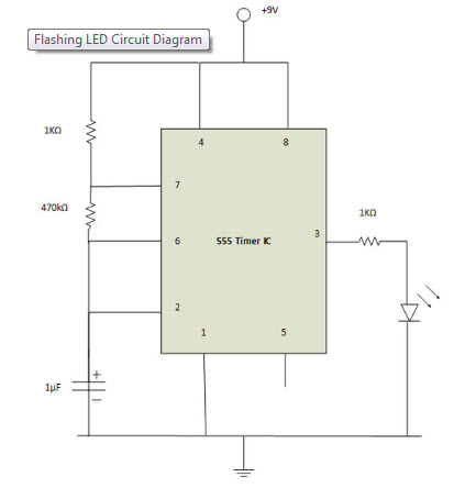
Making Of Flashing Blinking Led Circuit Diagram Using 555 Timer Ic from www.elprocus.com Using the 555 timer ic in special or unusual circuits. Daman shah june 5, 2021. 555 timer is an industrial standard ic existing from early days of ic. The 555 timer is a simple integrated circuit that can be used to make many different electronic circuits. In this mode, the circuit of the ic 555 timer produces the continuous pulses with exact frequency primarily based on the value of the two resistors and. Circuit diagram of flash lamp using 555 timer ic. Once this switch is pushed, the circuit pulls its output to a. We have a large collection of simple and advanced projects using 555 timer ic.
555 timer bistable example circuit.
We have seen in the last few tutorials that the 555 timer can be configured with externally connected components as multivibrators, oscillators and timers, with timing intervals ranging from a few microseconds to many hours. One reduces the trigger sensitivity and the other will double the output pulse duration without increasing the r1 and c1 values. The working modes of a 555 timer are astable, bistable, and monostable. This is a 555 one shot timer circuit. Supply voltage requirements range from 3 to 18 volts, making the 555 one of the most versatile integrated circuits available. 500ms is the same as saying 0.5s so by rearranging the formula above, we get the calculated value for the resistor, r as: Daman shah june 5, 2021. This enables the 555 to operate as a window detector. Here is a simple and interesting hobby circuit that can be made using the popular 555 timer ic. The 4rth circuit diagram shows the standard ic 555 adjustable timer circuit having two sets of timing ranges and an output relay for toggling the desired load. The block diagram of a 555 timer is shown in the above figure. Working modes of 555 timer ic. 555 timer bistable example circuit.


0 Komentar